How to Build an Arduino UNO Smart Robot Car
1. Prepare the Robot Cars DC Motors
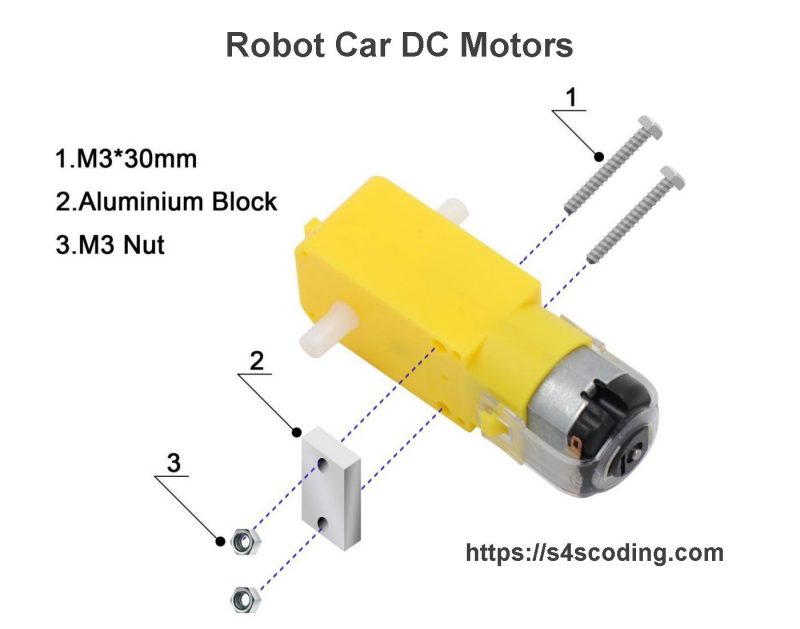
Step 1 is prepare the 4 robot car DC motors for installation onto the robot cars bottom acrylic chassis base.
For each DC motor you will need:
- 1x Robot Car DC Motor
- 2x M3*30mm Bolts
- 2x M3 Nuts
- 1x Aluminum Block
The Arduino UNO car kit is well organised, all the aluminum blocks and bolts/nuts for step 1 and step 2 are held in a single zip lock bag with a Motor: label listing the contents.
Robot Car DC Motors Notes
Not shown in the image above, the motors each have two wires soldered to the DC motors ready to attach to the L298N Motor Driver Board. Place the Aluminum Block on the same side as the soldered wires so when the smart robot car is complete the wires are safely stored on the inside of the car so the solder is less likely to be broken when in use.
2. Smart Robot Car Kit DC Motors Installation
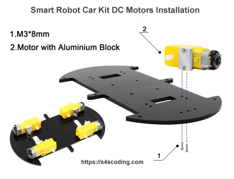
Step 2 is to attach the prepared DC motors from step 1 onto the robot cars bottom acrylic chassis base.
You will need:
- 4x Prepared Robot Car DC Motors
- 8x M3*8mm Bolts
- 1x Bottom Acrylic Chassis Base
The 8x M3*8mm bolts are within the same zip lock bag as the aluminum blocks etc… from step 1.
Attach each prepared robot DC motor onto the robot cars bottom acrylic chassis base (with two M3*8mm bolts each) so the aluminum blocks and motors wires are on the inside and the visible metal parts of the DC motors are located on the outside ‘corners’ of the bot.
Smart Robot Car Kit DC Motors Installation Notes
The M3*8mm bolts screw into the aluminum blocks, if you find they don’t screw in easily try to avoid forcing, they could cross thread. The aluminum blocks have bolt holes on both sides, try detaching the aluminum block (reverse Step 1), turn the aluminum block around so the other two bolt holes are used instead.
The robot cars bottom acrylic chassis base is quite sturdy, but it is acrylic, if you over tighten the bolts the acrylic could be damaged.
3. Attach the Arduino L298N Motor Driver Circuit Board
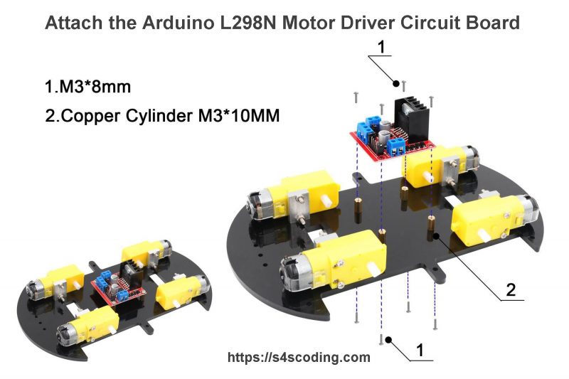
Step 3 is to attach the Arduino L298N motor driver circuit board onto the robot cars bottom acrylic chassis base.
You will need:
- 8x M3*8mm Bolts
- 4x Copper Cylinder Nuts
- 1x Arduino L298N Motor Driver Circuit Board
- 1x Bottom Acrylic Chassis Base from Step 2
The zip lock bag labeled L298, UNOR3 contains enough copper cylinder nuts and M3*8mm bolts to attach the Arduino L298N motor driver circuit board (Step 3) and the Arduino UNO clone (Step ???).
Attach 4 copper cylinder nuts to the bottom acrylic chassis base with 4 M3*8mm bolts, rest the Arduino L298N motor driver circuit board on top of the copper cylinder nuts and secure with 4 M3*8mm bolts as shown in the image above.
The Arduino L298N circuit board contains two complete H-Bridge motor driver circuits, so it is capable of driving a pair of DC motors. This makes it ideal for robotic projects, as most robots have either two or four powered wheels. The circuit board can drive DC motors that have voltages between 5V and 35V, with a peak current of up to 2A.
Attach the Arduino L298N Motor Driver Circuit Board Notes
When attaching the copper cylinder nuts to the acrylic chassis base don’t fully tighten the bolts until you’ve connected the L298N motor driver board with all 4 bolts. This will give you some wiggle room for aligning the copper cylinder nuts to the M3*8mm bolts.
4. Connect the Robot Car DC Motors Wires to the Arduino L298N Motor Driver Circuit Board
Step 4 is to wire the 4 robot DC motors into the Arduino L298N motor driver circuit board.

